L298N Motor Driver

l298N motor driver
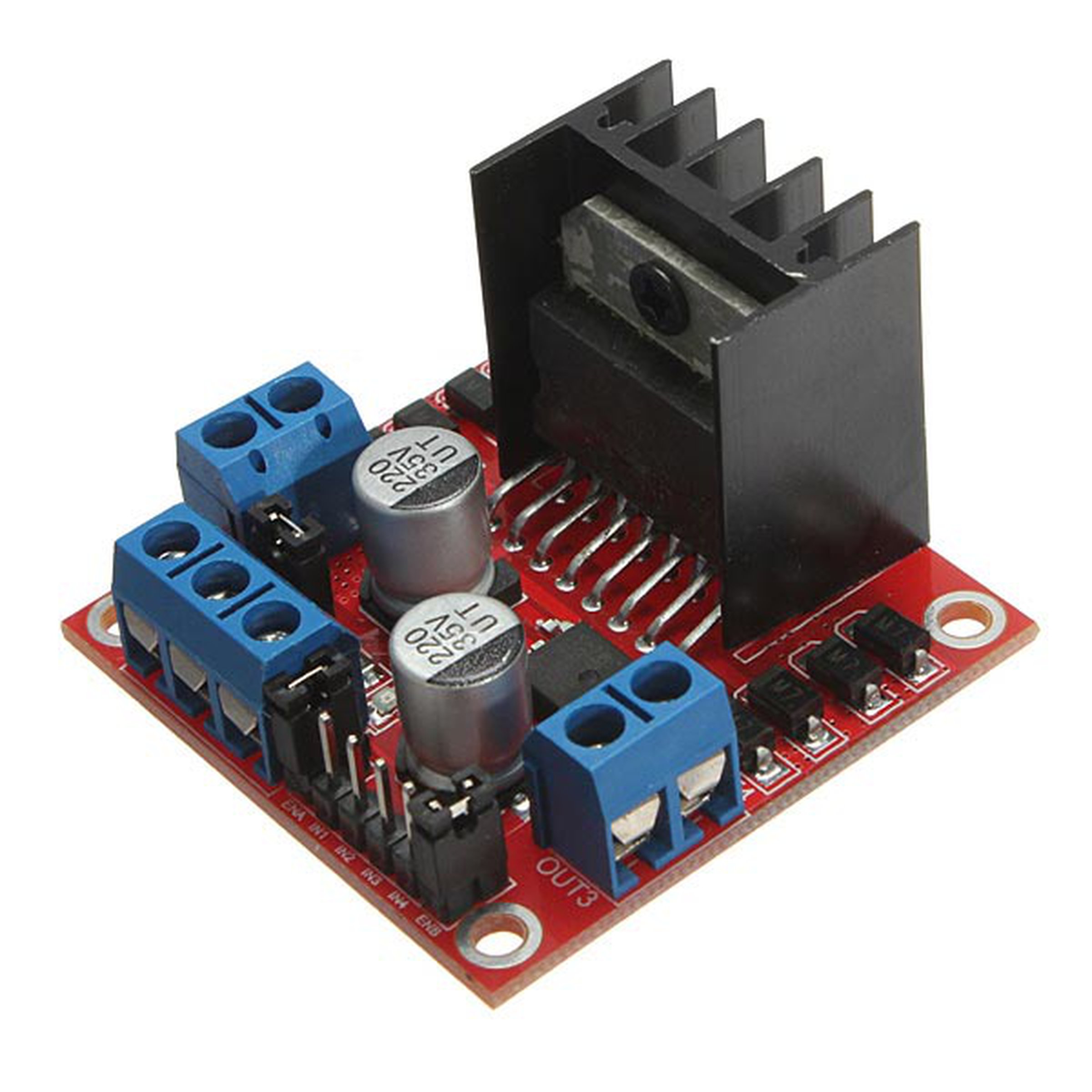
L298N motor driver board module; It can directly drive two 3-30V DC motors and can also provide a 5V output interface. It can also provide 5V single-chip circuit to support 3.3VMCU control. With this card module, you can easily control DC motor speed and direction. In addition, it can be easily controlled by a 2-phase stepper motor used in smart vehicles. You can do it yourself by examining the 2WD robot car project using the L298N module.
Technical Specifications of l298N motor driver Board Module
Driver: L298N Double H Bridge DC Motor Driver IC Driven part of terminal supply area
Vs: +5V ~ +35
V; Feeding area that needs power
Vs: +7 V ~ +35 V Highest current Driven part of Io (logical part of 2A Terminal supply area)
Vss: +5 V ~ +7 V (inside the board can be powered by +5 V) Logical part of the operating current range: 0 ~ 36mA Control signal input voltage range: Low: -0.3V High: 2.3V Enable signal input voltage range: Low: -0.3 High: 2.3V Maximum power consumption: 20W (when temperature T = 75 Deg C)
Operating Ambient Temperature; -25 Deg C ~ +130 Deg C
Other Extensions; control of direction indicators, logic part of the plate to receive the power interface.
Driver Board Module Size; 55mm*60mm*30mm
Driver Card Weight: 33 g
Use of; H-Bridges are typically used to control the speed and direction of motors but can also be used for other different projects such as being able to drive the brightness of lighting projects such as high power LEDs in some projects.
How the l298N motor driver Board Works
H-Bridge is a modular circuit board that can drive a current in both polarities and can be controlled by pulse width modulation, that is, pwm, and is frequently used in projects.
Pulse Width Modulation is actually the determination of controlling the duration of an electronic pulse that occurs. If we imagine the brush in the motors as a rotating mill and the resulting current as water flowing on this mill; Let’s express the water flowing over the wheel at a constant rate as voltage. The more water flows, the higher the voltage will be. All of the motors used in the projects are scaled within a certain voltage range. In practice, the motor and circuit may be damaged if too much voltage is applied and/or if the value is rapidly reduced to slow the motor down suddenly. When we consider the pwm application as the analogy of the waterwheel in the mill. Increasing the voltage at certain rates and decreasing it at certain rates, just like the water transferred to the mill, will ensure that the motors used in the projects have a longer life. The longer the pulses, the faster the mill wheel rotates. The shorter the pulses, the slower the mill wheel rotates.
Projelerde motorların PWM ile kontrol edilmesi önerilir. Böylece motorlar çok daha uzun süre dayanacaktır.
l298N motor driver Onboard Inputs/Outputs
Output 1: Motor A output Output 2: Motor A output Output 3: Motor B output Output 4: Motor B output Voltage  It can actually be between 5v-35v, here it is only marked as 12v.
GND: Earth
EnA: Activates pwm signal for motor A
In1: Activates motor A
In2: Activates motor A
EnB: Activates pwm signal for motor B
In3: Activates motor B
In4: Activates motor B