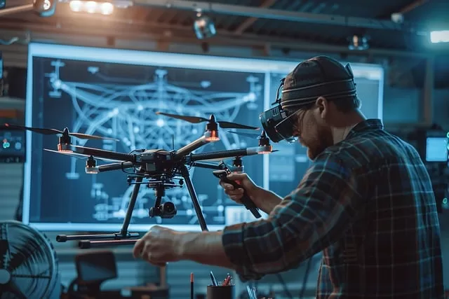
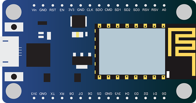
To make a drone with Arduino, you’ll need a combination of hardware and software. Here’s a general guide on how to build a basic quadcopter drone using Arduino:
Components:
1. Arduino board (e.g., Arduino Uno, Nano, or Mega)
2. Brushless motors (4x)
3. Electronic Speed Controllers (ESCs) (4x, one for each motor)
4. Quadcopter frame (or you can build one yourself)
5. Propellers (2x clockwise, 2x counterclockwise)
6. IMU (Inertial Measurement Unit) sensor (like MPU6050 for gyroscope/accelerometer)
7. RC Transmitter and Receiver (for remote control)
8. Li-Po battery (with a suitable power rating for the motors)
9. Power Distribution Board (PDB) (to power the ESCs and motors)
10. Battery Elimination Circuit (BEC) (optional, for regulating voltage to Arduino)
11. Wires and connectors
12. Screws, nuts, and zip ties
Steps to Build the Drone:
1. Assemble the Quadcopter Frame:
Start by mounting the motors onto the drone frame.
Attach the propellers to the motors (make sure to use clockwise and counterclockwise propellers on the correct motors).
2. Install the ESCs
Connect each ESC to the corresponding motor.
The ESCs are responsible for controlling the speed of each motor.
Connect the ESCs’ power leads to the Power Distribution Board (PDB) and connect the signal leads to the Arduino.
3. Connect the IMU Sensor:
Mount the MPU6050 IMU sensor on the drone to monitor the orientation (yaw, pitch, roll).
Wire the IMU sensor to the Arduino board (SCL, SDA, GND, VCC).
4. Set Up the Arduino:
Connect the Arduino to your computer and upload the flight control software.
You can either write your own code or use an existing library, such as MultiWii or ArduPilot for Arduino-based flight control.
5. Wire the Components:
Connect the ESC signal wires to the Arduino’s PWM pins (for example, pins 3, 5, 6, and 9).
Connect the IMU sensor (MPU6050) to the Arduino’s I2C pins (A4 for SDA, A5 for SCL on the Uno).
Connect the RC Receiver channels to the Arduino (typically, throttle, yaw, pitch, and roll channels).
6. Power Supply:
Connect the Li-Po battery to the Power Distribution Board (PDB) to provide power to the ESCs and Arduino.
If using a BEC, connect it to regulate the voltage going into the Arduino (if the battery voltage exceeds 5V).
7. Upload the Code:
Write the code to control the drone, or use a pre-built firmware like MultiWii.
The code should:
Read signals from the RC receiver.
Process the data from the IMU sensor to maintain stability (PID control loop).
Adjust motor speeds through the ESCs based on input from the RC transmitter and the IMU feedback.
8. Test and Calibrate:
Test the IMU sensor and calibrate it to ensure the drone is stable.
Test the motors and ESCs to ensure proper rotation and responsiveness.
Calibrate the ESCs to match the throttle range from the RC transmitter.
9. Final Assembly:
Secure all wiring to avoid interference with moving parts (motors and propellers).
Mount the battery on the frame and ensure the center of gravity is balanced.
10. Flight Test:
Power on the drone, connect the RC transmitter, and perform a controlled flight test.
Adjust the PID (Proportional, Integral, Derivative) parameters in the code to improve flight stability.
Example Arduino Code (Simplified):
#include <Wire.h>
#include <MPU6050.h>
MPU6050 mpu;
void setup() {
Serial.begin(115200);
Wire.begin();
mpu.initialize();
// Check MPU6050 connection
if (!mpu.testConnection()) {
Serial.println(“MPU6050 connection failed!”);
}
}
void loop() {
// Code to control motors based on RC signals and MPU data
int16_t ax, ay, az;
int16_t gx, gy, gz;
mpu.getMotion6(&ax, &ay, &az, &gx, &gy, &gz);
// Use data from MPU to calculate orientation
// Apply PID control for motor adjustments
// Send PWM signals to ESCs
}
Important Considerations:
Stability: You’ll need to tune the PID controller to get stable flight.
Power: Ensure your power distribution is solid to prevent voltage drops or overloading.
Failsafe: Implement failsafe mechanisms in the code to prevent crashes in case of signal loss.
Buildinga an Arduino-based drone can be challenging but rewarding. Once you have the basics down, you can add features like GPS, altitude hold, or autonomous flight modes.
To control a drone using a mobile phone with Arduino, we can use a Bluetooth module such as HC-05 or HC-06. This detailed implementation includes setting up communication between your phone and the Arduino-based drone via Bluetooth and controlling its flight modes (e.g., takeoff, land, pitch, roll, yaw, and throttle).
Components:
Arduino Uno/Nano/Mega
Bluetooth module (HC-05 or HC-06)
MPU6050 (Accelerometer and Gyroscope)
4 Brushless Motors
4 ESCs (Electronic Speed Controllers)
Li-Po battery
Frame and Propellers
Battery for powering ESCs
Mobile phone (for Bluetooth control using apps like Bluetooth Terminal or a custom app)
Wiring:
1. Bluetooth Module Wiring:
VCC to 5V
GND to GND
TX to RX of Arduino
RX to TX of Arduino
2. ESC and Motors Wiring:
Connect each motor to its respective ESC.
Connect the signal wires from ESCs to PWM pins on Arduino (e.g., 3, 5, 6, 9).
3. MPU6050 Wiring:
VCC to 5V
GND to GND
SDA to A4 (on Arduino Uno)
SCL to A5 (on Arduino Uno)
Software Libraries Required:
MPU6050: Library for reading data from the MPU6050 sensor.
Servo.h: Used to control the ESCs.
To install these libraries, go to Sketch > Include Library > Manage Libraries in the Arduino IDE, then search for and install MPU6050 and Servo libraries.
Full Drone Control Code:
#include <Wire.h>
#include <MPU6050.h>
#include <Servo.h>
#include <SoftwareSerial.h>
MPU6050 mpu;
Servo motor1, motor2, motor3, motor4;
SoftwareSerial BT(10, 11); // Bluetooth on pins 10 (RX), 11 (TX)
int throttle = 1000; // Initial throttle for motors
int yaw = 0, pitch = 0, roll = 0;
float Kp = 1.0, Ki = 0.0, Kd = 0.0;
float pitchSetpoint = 0, rollSetpoint = 0, yawSetpoint = 0;
float pitchValue, rollValue, yawValue;
float lastPitchError = 0, lastRollError = 0, lastYawError = 0;
float pitchIntegral = 0, rollIntegral = 0, yawIntegral = 0;
void setup() {
Serial.begin(115200);
BT.begin(9600); // Initialize Bluetooth communication
motor1.attach(3); // Connect ESCs to PWM pins
motor2.attach(5);
motor3.attach(6);
motor4.attach(9);
Wire.begin();
mpu.initialize();
if (!mpu.testConnection()) {
Serial.println(“MPU6050 connection failed!”);
while (1);
}
// Initialize motors at minimum throttle
motor1.writeMicroseconds(throttle);
motor2.writeMicroseconds(throttle);
motor3.writeMicroseconds(throttle);
motor4.writeMicroseconds(throttle);
}
void loop() {
int16_t ax, ay, az;
int16_t gx, gy, gz;
// Read MPU6050 sensor data
mpu.getMotion6(&ax, &ay, &az, &gx, &gy, &gz);
pitchValue = atan2(ay, az) * 180 / PI; // Calculate pitch angle
rollValue = atan2(ax, az) * 180 / PI; // Calculate roll angle
// Read commands from Bluetooth
if (BT.available()) {
char command = BT.read();
handleBluetoothCommand(command); // Process command
}
// Apply PID for pitch
float pitchError = pitchSetpoint – pitchValue;
pitchIntegral += pitchError;
float pitchDerivative = pitchError – lastPitchError;
float pitchOutput = Kp * pitchError + Ki * pitchIntegral + Kd * pitchDerivative;
lastPitchError = pitchError;
// Apply PID for roll
float rollError = rollSetpoint – rollValue;
rollIntegral += rollError;
float rollDerivative = rollError – lastRollError;
float rollOutput = Kp * rollError + Ki * rollIntegral + Kd * rollDerivative;
lastRollError = rollError;
// Motor speed adjustments based on PID output
int motor1Speed = throttle + pitchOutput – rollOutput;
int motor2Speed = throttle – pitchOutput – rollOutput;
int motor3Speed = throttle – pitchOutput + rollOutput;
int motor4Speed = throttle + pitchOutput + rollOutput;
// Write motor speeds
motor1.writeMicroseconds(constrain(motor1Speed, 1000, 2000));
motor2.writeMicroseconds(constrain(motor2Speed, 1000, 2000));
motor3.writeMicroseconds(constrain(motor3Speed, 1000, 2000));
motor4.writeMicroseconds(constrain(motor4Speed, 1000, 2000));
delay(20); // Small delay for stability
}
void handleBluetoothCommand(char command) {
switch (command) {
case ‘u’: // Increase throttle
throttle = constrain(throttle + 50, 1000, 2000);
Serial.println(“Throttle increased”);
break;
case ‘d’: // Decrease throttle
throttle = constrain(throttle – 50, 1000, 2000);
Serial.println(“Throttle decreased”);
break;
case ‘l’: // Yaw left
yawSetpoint -= 10;
Serial.println(“Yaw left”);
break;
case ‘r’: // Yaw right
yawSetpoint += 10;
Serial.println(“Yaw right”);
break;
case ‘f’: // Pitch forward
pitchSetpoint += 5;
Serial.println(“Pitch forward”);
break;
case ‘b’: // Pitch backward
pitchSetpoint -= 5;
Serial.println(“Pitch backward”);
break;
case ‘a’: // Roll left
rollSetpoint -= 5;
Serial.println(“Roll left”);
break;
case ‘s’: // Roll right
rollSetpoint += 5;
Serial.println(“Roll right”);
break;
case ‘t’: // Takeoff (set throttle to hover)
throttle = 1500;
Serial.println(“Takeoff”);
break;
case ‘q’: // Land (reduce throttle)
throttle = 1000;
Serial.println(“Land”);
break;
default:
Serial.println(“Unknown command”);
break;
}
}
Key Functions:
1. handleBluetoothCommand(char command): Handles commands from the mobile phone via Bluetooth.
u: Increase throttle (ascend)
d: Decrease throttle (descend)
f: Pitch forward
b: Pitch backward
l: Yaw left
r: Yaw right
a: Roll left
s: Roll right
t: Takeoff (set throttle to hover)
q: Land
2. MPU6050 integration: Used for balancing the drone (pitch and roll control).
3. Throttle and motor control: The throttle controls the motor speeds, and the PID outputs for pitch and roll are used to adjust individual motor speeds for stability.
How to Control the Drone via Mobile Phone:
1. Download a Bluetooth terminal app on your mobile phone.
2. Pair your phone with the Bluetooth module (HC-05/HC-06).
3. Open the Bluetooth terminal and connect to the Bluetooth module.
4. Send the appropriate commands (u, d, f, b, l, r, t, q) to control the drone.
Notes:
Make sure the ESCs are calibrated correctly before flying.
Adjust the PI
D values for smooth flight based on your drone’s setup.
Test in a safe and open area to avoid any damage.
This setup allows you to control the drone’s throttle, yaw, pitch, and roll using your mobile phone, enabling basic flight control modes.


