Here’s a detailed guide on simple and low-cost robotic applications using non-Arduino components, perfect for beginners or education projects.
Build Cool Robots Using Simple Electronics
🧭 Introduction
You don’t always need an Arduino or Raspberry Pi to get started with robotics. In fact, basic electronic components like transistors, relays, sensors, and motor drivers can help you build fully functional robots. These projects are great for education, beginners, or low-budget environments.
In this guide, we’ll explore 3 fun and educational robotic projects you can build using only simple components—no programming required!
🔧 What You’ll Learn
- How to build robots using transistors, relays, LDRs, and 555 timers
- Simple wiring diagrams and principles
- How each robot behaves based on sensor input
- How to prototype without a microcontroller
⚠️ Attention !
Before starting any project implementation, please read the Safety & Legal Disclaimer section at the bottom of this page. It contains important guidelines to ensure safe and responsible usage.
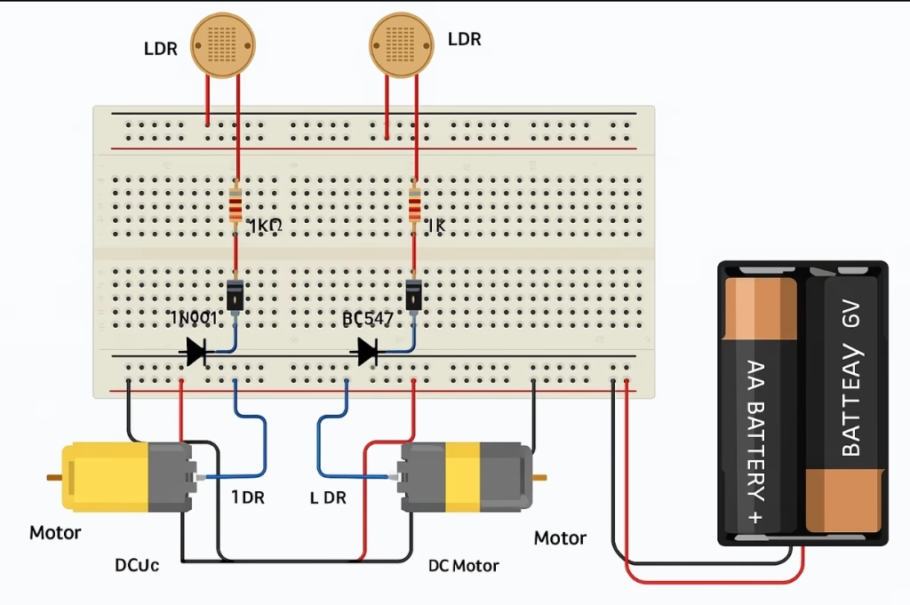
🛠️ Project 1: Light-Following Robot (No Microcontroller)
📦 Components
- 2 x DC Motors with wheels
- 2 x LDRs (Light Dependent Resistors)
- 2 x NPN Transistors (e.g., BC547 or 2N2222)
- 2 x Diodes (e.g., 1N4001)
- 2 x Resistors (1kΩ)
- 1 x Battery pack (4x AA or 6V)
- Wires and Breadboard or PCB
🔌 Circuit Overview
- Each LDR is connected to a transistor’s base with a resistor.
- When light hits the LDR, resistance drops → base current flows → motor activates.
- Two sides work independently.
🧠 Working Principle
- When light shines more on one side, that motor turns ON and the robot turns toward the light.
- Balanced light = forward movement.
📷 Top View Circuit Diagram (Textual)
[LDR Left] → [1kΩ] → [BC547 Transistor Left Base]
                           |→ Motor Left → GND

[LDR Right] → [1kΩ] → [BC547 Transistor Right Base]
                           |→ Motor Right → GND
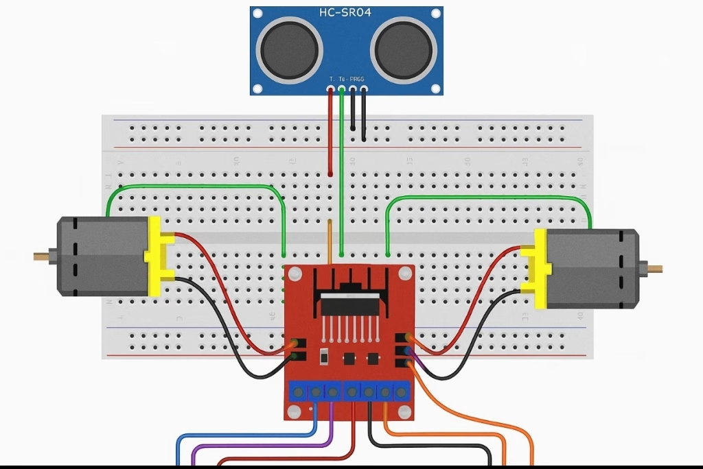
🛠️ Project 2: Obstacle Avoiding Robot Using Relays
📦 Components
- 2 x SPDT Relays
- 2 x IR Obstacle Sensors (like TCRT5000 modules)
- 2 x DC Motors
- 2 x Diodes (Flyback, e.g., 1N4007)
- 1 x Power source (6V battery)
- Breadboard or PCB
🔌 Circuit Logic
- Each IR sensor controls a relay.
- When an object is detected, the relay cuts power to the motor on that side.
- This causes the robot to turn away from the object.
🧠 Working Principle
- If both IRs detect clear path → go forward
- If right sensor detects an object → left motor ON only → robot turns left
- If both detect obstacle → stop or reverse (optional feature with SPDT relays)
Great! Since Project 2: Obstacle Avoiding Robot Using Relays is designed to work without a microcontroller, it doesn’t require or use any code. The entire system works based on analog logic using IR sensors and SPDT relays.
However, I’ll provide:
- ✅ A clear explanation of how the logic works
- 🛠️ An optional version with code, if you’d prefer to use a microcontroller later (e.g., ATtiny85 or Arduino Nano)
✅ Relay-Based Logic System (NO CODE)
This version uses:
- IR sensors → detect objects
- Relays → act as automatic switches
- Motors → get power depending on sensor input
🔌 Wiring Summary:
- IR Sensor Right OUT → controls Relay Right Coil
- Relay Right Normally Closed (NC) → Right Motor ON
- If sensor detects obstacle → signal energizes relay → switch moves → cuts power to Right Motor
Same logic applies for left side.
🧠 Robot Behavior Table:
🤖 Robot Behavior Summary
| 👁️ L | 👁️ R | ⚙️ ML | ⚙️ MR | 🚗 Action |
|---|---|---|---|---|
| 0 | 0 | ON | ON | ▶️ Forward |
| 1 | 0 | OFF | ON | ↩️ Turn Right |
| 0 | 1 | ON | OFF | ↪️ Turn Left |
| 1 | 1 | OFF | OFF | ⛔ Stop / Reverse |
⚠️ No microcontroller, no code — the IR sensor’s output directly switches the relays, which either connect or disconnect power to the motors.
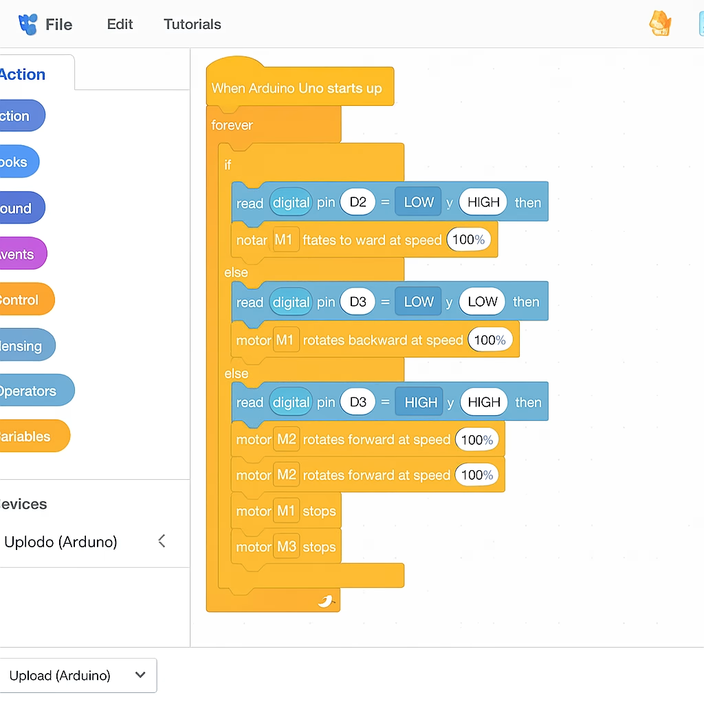
🛠️ Optional Version with Code (Arduino Nano / ATtiny85)
If you’d rather use a microcontroller for more control or better response, here’s a simple version in Arduino IDE.
📦 Extra Components:
- Arduino Nano (or ATtiny85)
- 2 Digital inputs (for IR sensors)
- 2 Digital outputs (to control relay modules)
🧾 Code:
#define irLeft A0      // Left IR sensor
#define irRight A1     // Right IR sensor
#define relayLeft 3    // Left motor relay
#define relayRight 4   // Right motor relay

void setup() {
  pinMode(irLeft, INPUT);
  pinMode(irRight, INPUT);
  pinMode(relayLeft, OUTPUT);
  pinMode(relayRight, OUTPUT);
}

void loop() {
  int leftSensor = digitalRead(irLeft);
  int rightSensor = digitalRead(irRight);

  // Default state: both relays ON = go forward
  if (leftSensor == LOW && rightSensor == LOW) {
    digitalWrite(relayLeft, HIGH);
    digitalWrite(relayRight, HIGH);
  }
  // Obstacle on left → stop left motor
  else if (leftSensor == HIGH && rightSensor == LOW) {
    digitalWrite(relayLeft, LOW);
    digitalWrite(relayRight, HIGH);
  }
  // Obstacle on right → stop right motor
  else if (leftSensor == LOW && rightSensor == HIGH) {
    digitalWrite(relayLeft, HIGH);
    digitalWrite(relayRight, LOW);
  }
  // Both blocked → stop
  else {
    digitalWrite(relayLeft, LOW);
    digitalWrite(relayRight, LOW);
  }

  delay(50);  // Stability delay
}
🔧 Optional Features You Can Add
- Reverse for 1 second if both sensors detect → then turn.
- Add buzzer when object detected.
- Use PWM (via transistor) for speed control.
🛠️ Project 3: Line-Follower Robot Using 555 Timers
📦 Components
- 2 x IR Reflective Sensors
- 2 x DC Motors
- 2 x 555 Timers (as comparators or PWM generators)
- 2 x NPN Transistors or H-Bridge driver (L293D optional)
- Power source
- Black electrical tape (for the track)
🔌 Circuit Logic
- 555 timer works in comparator mode.
- IR sensor detects black line → changes voltage level
- This output triggers 555 output to control motors
🧠 Working Principle
- Follows a dark line on white surface.
- One motor turns off if the sensor on its side leaves the line.
Let’s walk through Project 3: Line-Follower Robot Using 555 Timers in detail. Since this version is designed to work without microcontrollers, we use 555 timer ICs as comparators or PWM motor controllers, which means:
👉 NO actual “code” is needed—just smart analog logic using simple components.
✅ Version 1: Pure Hardware Logic (No Code)
⚙️ How it works:
- IR reflective sensors detect the difference between black and white surfaces.
- Each IR sensor controls a 555 timer configured as a voltage comparator.
- The 555 output drives an NPN transistor, which switches ON/OFF the motor.
🔌 Circuit Configuration (One Side Example)
Each motor is controlled by its own IR sensor + 555 timer combo:
- IR Sensor OUT → connected to 555 timer pin 2 (Trigger)
- 555 Timer is powered by battery (VCC → pin 8, GND → pin 1)
- 555 Timer pin 3 (Output) → connected to base of NPN transistor via 1kΩ resistor
- Motor connected in series between VCC and transistor collector
- Transistor emitter → GND
If IR sensor detects white: Output LOW → motor ON
If IR sensor detects black line: Output HIGH → motor OFF
✳️ This way, when one side of the robot leaves the line, the motor on that side stops, causing the robot to turn back toward the line.

💡 Optional Upgrade: Using 555 Timer in PWM Mode (for smoother movement)
You can configure the 555 in astable mode to provide PWM output that changes based on IR sensor reading (voltage level → duty cycle).
In this case:
- IR sensor output adjusts the charging capacitor (via variable resistor or transistor)
- PWM duty cycle changes dynamically with sensor reading
- Motor speed varies smoothly as the robot follows curves
This design requires more complex tuning, but still no code.
🛠️ Still Want a Microcontroller Version?
If you prefer a code-based solution using Arduino (or ATtiny85), here’s a sample:
#define irLeft A0
#define irRight A1
#define motorLeft1 3
#define motorRight1 4

void setup() {
  pinMode(irLeft, INPUT);
  pinMode(irRight, INPUT);
  pinMode(motorLeft1, OUTPUT);
  pinMode(motorRight1, OUTPUT);
}

void loop() {
  int leftVal = digitalRead(irLeft);
  int rightVal = digitalRead(irRight);

  if (leftVal == LOW && rightVal == LOW) {
    // Both sensors on white = forward
    digitalWrite(motorLeft1, HIGH);
    digitalWrite(motorRight1, HIGH);
  } else if (leftVal == HIGH && rightVal == LOW) {
    // Left sees black = turn right
    digitalWrite(motorLeft1, LOW);
    digitalWrite(motorRight1, HIGH);
  } else if (leftVal == LOW && rightVal == HIGH) {
    // Right sees black = turn left
    digitalWrite(motorLeft1, HIGH);
    digitalWrite(motorRight1, LOW);
  } else {
    // Both on black = stop
    digitalWrite(motorLeft1, LOW);
    digitalWrite(motorRight1, LOW);
  }
}

📌 Summary: | Version | Needs Code? | Components | Complexity | |——————–|————-|—————————–|————| | 555 comparator | ❌ No | IR sensor + 555 + transistor| Easy | | 555 PWM (advanced) | ❌ No | IR sensor + tuned PWM circuit| Medium | | Arduino version | ✅ Yes | IR sensor + Arduino | Easy |
💡 Tips for Success
- Use a cardboard chassis or recycled plastic.
- Mount motors with zip ties or glue.
- Keep wires short and organized.
- Test each sensor or relay circuit individually first.
📘 Educational Value
| Feature | Educational Benefit |
|---|---|
| No code | Focus on logic, sensors, circuit design |
| Analog components | Learn about voltage, resistance, current |
| Real-time response | See input/output relationship instantly |
| Breadboard-based | Fast prototyping, easy modification |
🎓 Conclusion
You can create impressive robotic projects with zero programming and low-cost components. These types of robots are great for introducing young students or DIYers to automation and electronics before they jump into microcontrollers like Arduino.
⚠️ Safety & Legal Disclaimer
This project is for educational and prototyping purposes only.
- AI logic should be carefully tested before being automatically implemented.
- All operations and applications performed in these projects are the responsibility of the project developer.
- For real-world applications, the system must be equipped with sensors, protective enclosures, and comply with legal regulations.
- Any resulting damage, misuse, or misinterpretation of data, devices, or others is the sole responsibility of the user.
Please use the project responsibly and conduct thorough testing before field implementation.
Supervision and Control
It is strongly recommended that children, especially those with limited electronic knowledge, work under the constant supervision and control of an adult or experienced professional when engaging with such projects.


")