🌟 What’s Possible Today?
Arduino is not just a microcontroller — it’s a gateway to innovation. From hobbyists to engineers, makers around the world are pushing boundaries with Arduino-powered inventions. In this article, we’ll explore some of the most creative and groundbreaking ideas made with Arduino — from wearable tech to environmental solutions.
🔍 What Makes Arduino So Powerful for Innovation?
Arduino offers:
- Open-source hardware & software
- Affordable components
- A huge community of developers
- Compatibility with various sensors, actuators, and wireless modules
These features make it the perfect platform for prototyping and inventing.
⚠️ Attention!
Before starting any project implementation, please read the Safety & Legal Disclaimer section at the bottom of this page. It contains important guidelines to ensure safe and responsible usage.
🚀 Top Innovative Arduino-Based Inventions
1. 🧠 Smart Brain-Controlled Wheelchair
Using Arduino + EEG sensors, inventors have built wheelchairs that respond to brainwaves. A person can control movement simply by thinking — a life-changer for people with mobility disabilities.
Core components:
- Arduino Uno
- EEG Brainwave Sensor
- Motor Driver
- Wheelchair motors
Here is a detailed step-by-step web-format guide for building a Smart Brain-Controlled Wheelchair using Arduino and an EEG brainwave sensor:
🧠 Smart Brain-Controlled Wheelchair (EEG + Arduino)
🚀 Introduction
A Smart Brain-Controlled Wheelchair enables users to move the chair with thoughts using EEG brainwave signals. Designed for people with limited mobility, this project combines neuroscience and robotics to promote independence and accessibility.
🧩 Components Required
| Component | Quantity | Description |
|---|---|---|
| Arduino Uno | 1 | Main microcontroller for control |
| EEG Brainwave Sensor | 1 | Reads brainwave signals (e.g., NeuroSky MindWave) |
| L298N Motor Driver | 1 | Drives the motors |
| DC Motors (wheelchair) | 2 | For forward and backward movement |
| Wheels with frame | 2 | Attached to the motors |
| 12V Battery Pack | 1 | Power supply for motors and Arduino |
| Jumper Wires | As needed | Connections between components |
| Breadboard | Optional | For prototyping |
| Bluetooth Module (HC-05) | 1 | Optional – for wireless communication |
🧠 How It Works
- Brainwaves are measured using an EEG sensor.
- Sensor sends data to Arduino Uno.
- Arduino interprets brain signals like concentration or blinking.
- Based on signal thresholds, Arduino sends commands to motor driver.
- Wheelchair motors respond — move forward, stop, or turn.
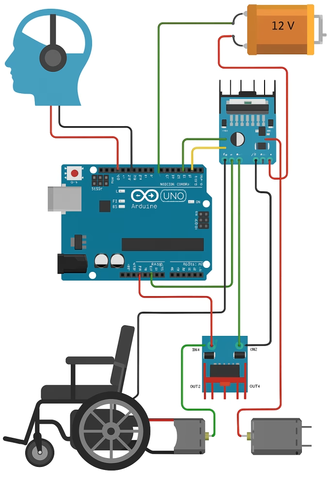
🔌 Circuit Diagram
[EEG Sensor] --> [Arduino Uno] --> [L298N Motor Driver] --> [DC Motors]
                           |
                        [Battery]
- EEG TX → Arduino RX
- Arduino D8/D9 → L298N IN1/IN2
- L298N OUT1/OUT2 → Left Motor
- L298N OUT3/OUT4 → Right Motor
- 12V → Motor VCC, 5V → Arduino + EEG
👨💻 Arduino Code (Sample – Brainwave Threshold Control)
#include <SoftwareSerial.h>

SoftwareSerial eeg(2, 3); // RX, TX
int motorPin1 = 8;
int motorPin2 = 9;

void setup() {
  Serial.begin(9600);
  eeg.begin(9600);
  pinMode(motorPin1, OUTPUT);
  pinMode(motorPin2, OUTPUT);
}

void loop() {
  if (eeg.available()) {
    int attention = eeg.read(); // hypothetical value from EEG

    if (attention > 60) {
      digitalWrite(motorPin1, HIGH);
      digitalWrite(motorPin2, LOW);
      Serial.println("Moving forward");
    } else {
      digitalWrite(motorPin1, LOW);
      digitalWrite(motorPin2, LOW);
      Serial.println("Stopped");
    }
  }
}
Note: Real EEG sensors like NeuroSky or OpenBCI require proper SDK/parsing for reliable signal processing.
🛠️ Step-by-Step Build
1. Set Up the EEG Sensor
- Connect EEG module to Arduino using
SoftwareSerialpins. - Make sure baud rate matches sensor documentation.
2. Wire the Motor Driver
- Connect IN1, IN2, IN3, IN4 to Arduino digital pins (e.g., D8–D11).
- Connect motors to OUT1–OUT4.
- Power the L298N with 12V battery.
3. Program the Arduino
- Upload sample code.
- Modify
attentionthreshold or add blink detection if your EEG supports it.
4. Test Movement
- Wear the EEG headset.
- Focus to trigger forward movement.
- Relax to stop.
5. Optional: Add Bluetooth Control
- Allow caregivers to override or assist via mobile app.
Safety Precautions section with additional advisory notes
⚠️ Safety Precautions
- Test in a controlled environment.
- Ensure an emergency stop switch is accessible at all times.
- Add limiters to avoid excessive speed or unexpected turning.
- Double-check all wiring and connections to prevent malfunction.
- Consider installing bumpers or proximity sensors for obstacle detection.
🧠 Potential Upgrades
- Add voice control or joystick fallback.
- Integrate GPS tracking or obstacle detection (e.g., ultrasonic sensors).
- Use machine learning to better interpret complex EEG patterns.
📸 Project Image Suggestion
Concept illustration idea:
- A wheelchair with a brainwave headset icon above.
- Movement arrows around wheels.
- Connected components: Arduino → Motor Driver → Motors.
2. 🌍 Environmental Pollution Detector (Air + Water Quality Monitoring)
An IoT-enabled air and water pollution monitoring system using Arduino and sensors that collect real-time data and send alerts to smartphones.
Sensors used:
- MQ-135 Air Quality Sensor
- pH Sensor for water
- GSM or WiFi module
🧠 Project Overview
This IoT-based pollution monitoring system detects both air and water quality in real-time using sensors and sends alerts via Wi-Fi or GSM. It’s ideal for smart city, industrial, or environmental research applications.
🧩 Components Required
| Component | Quantity | Description |
|---|---|---|
| Arduino Uno or Mega | 1 | Main controller |
| MQ-135 Air Quality Sensor | 1 | Detects CO2, NH3, benzene, smoke, etc. |
| Analog pH Sensor | 1 | Measures water acidity/basicity |
| GSM Module (SIM800L) or ESP8266 | 1 | For sending data via SMS or internet |
| LCD Display (16×2) + I2C | 1 | To show live sensor values (optional) |
| Power Supply (9V/12V) | 1 | Powers the Arduino and modules |
| Breadboard + Jumper Wires | As needed | For connections |
🧪 Sensor Functionality
- MQ-135 Air Sensor: Detects air pollutants like CO₂, NH₃, smoke, and alcohol vapors.
- pH Sensor: Detects water acidity (0–14 scale). pH < 6.5 = Acidic
pH > 8.5 = Basic
6.5 ≤ pH ≤ 8.5 = Acceptable for drinking water.
🔌 Circuit Connections
🟢 MQ-135 Air Sensor
- VCC → 5V
- GND → GND
- AOUT → A0 (Analog pin)
🔵 pH Sensor
- VCC → 5V
- GND → GND
- AOUT → A1
📡 GSM Module (SIM800L) / ESP8266 (NodeMCU or via serial)
- TX → RX of Arduino
- RX → TX of Arduino
- External power required (e.g., 3.7V battery for SIM800L)
👨💻 Arduino Code (GSM SMS Example)
#include <SoftwareSerial.h>

SoftwareSerial gsm(7, 8); // RX, TX
int airPin = A0;
int phPin = A1;
int airValue, phValue;

void setup() {
  Serial.begin(9600);
  gsm.begin(9600);
  pinMode(airPin, INPUT);
  pinMode(phPin, INPUT);
  delay(1000);
}

void loop() {
  airValue = analogRead(airPin);
  phValue = analogRead(phPin);

  float voltage = phValue * (5.0 / 1023.0);
  float ph = 7 + ((2.5 - voltage) / 0.18); // Example pH calculation

  Serial.print("Air: "); Serial.println(airValue);
  Serial.print("pH: "); Serial.println(ph);

  if (airValue > 300 || ph < 6.5 || ph > 8.5) {
    gsm.println("AT+CMGF=1"); delay(1000);
    gsm.println("AT+CMGS=\"+1234567890\""); // Replace with your phone number
    delay(1000);
    gsm.print("Alert! Pollution levels abnormal.\nAir: ");
    gsm.print(airValue); gsm.print(", pH: "); gsm.print(ph);
    gsm.write(26); // End of message
  }

  delay(10000); // Read every 10 seconds
}
For Wi-Fi (ESP8266), you can send data to ThingSpeak, Blynk, or a custom server via HTTP POST instead of SMS.
🧪 Calibration Tips
- Calibrate the pH sensor with buffer solutions (e.g., pH 4.0, 7.0, 10.0).
- For MQ-135, compare readings in fresh outdoor air and polluted environments for thresholds.
🖥️ Optional LCD Display (16×2 I2C)
Show real-time values:
Air: 289
pH: 7.26
Wire I2C:
- SDA → A4, SCL → A5 (for Uno)
Use the LiquidCrystal_I2C library for display.
📱 Smartphone Alerts
- GSM: Sends SMS to predefined numbers.
- Wi-Fi: Sends data to the cloud (Blynk, Thingspeak, Firebase).
- Add mobile notifications with Blynk App or Pushbullet API.
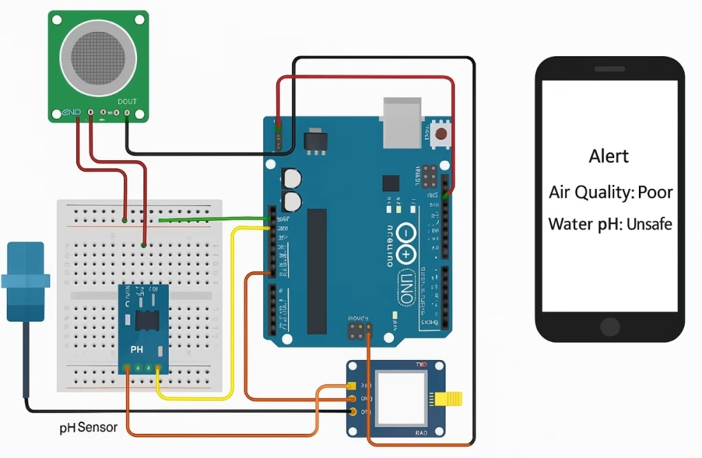
📸 Visual Concept
Suggested image idea:
- A city skyline in background
- Arduino board wired to gas sensor and a water test probe
- A phone receiving an alert
- Labels: “Air Quality: Poor”, “Water pH: Unsafe”
✅ Applications
- Smart cities
- Schools and universities (STEM education)
- Industrial pollution monitoring
- Rivers and lakes water quality logging
3. 🚰 🌿 Automated Plant Watering System (AI-Integrated)
Combining moisture sensors, Arduino, and even machine learning models, this system detects soil dryness and adapts watering behavior based on plant type and weather forecasts.
Great for: Smart agriculture, home gardens, vertical farming.
🌱 Project Overview
This smart irrigation system monitors soil moisture, predicts weather conditions, and adjusts watering frequency and quantity based on plant type and environmental data. It combines Arduino, moisture sensors, machine learning (ML) logic, and optional cloud connectivity.
Perfect for: Smart agriculture, home gardening, vertical farming, greenhouses
🧩 Required Components
| Component | Qty | Description |
|---|---|---|
| Arduino Uno or Mega | 1 | Main controller |
| Soil Moisture Sensor | 1+ | Detects soil dryness |
| Relay Module | 1 | Controls the water pump |
| Water Pump (DC or submersible) | 1 | Delivers water to plant |
| DHT11 / DHT22 Sensor | 1 | Temperature and humidity sensing (optional) |
| RTC Module (DS3231) | 1 | Real-time clock for scheduling (optional) |
| ESP8266 / GSM Module | 1 | For cloud/weather API (optional) |
| Plant Database (CSV/JSON) | – | Contains plant-specific water needs |
| Power Source (Battery/Solar) | 1 | Autonomous power supply |
| Tubing, container, wires | – | For water delivery system |
🧠 System Logic
- Sensor Input:
- Soil moisture level (0–1023)
- Air temperature & humidity
- Optional: Rain forecast from web API
- Decision Engine (Simple AI/ML):
- Based on plant type, current moisture, and expected rain:
- If soil is too dry AND no rain expected → Water plant.
- If plant is succulent → Delay watering longer.
- Adjust water amount & timing based on database rules.
- Based on plant type, current moisture, and expected rain:
- Watering Execution:
- Activate pump via relay
- Water for X seconds
- Log action (to SD card or cloud)
🔌 Wiring Summary
🌾 Soil Moisture Sensor
- AOUT → A0
- VCC → 5V
- GND → GND
💧 Water Pump (via Relay)
- Relay IN → D7
- VCC → 5V
- GND → GND
- Pump V+ → Relay COM
- Pump GND → Power Supply GND
🌡️ DHT11/DHT22
- DATA → D2
- VCC → 5V
- GND → GND
👨💻 Sample Arduino Code (Basic Logic)
#include <DHT.h>
#define DHTPIN 2
#define DHTTYPE DHT11
#define moisturePin A0
#define pumpPin 7

DHT dht(DHTPIN, DHTTYPE);

void setup() {
  Serial.begin(9600);
  pinMode(pumpPin, OUTPUT);
  dht.begin();
}

void loop() {
  int moisture = analogRead(moisturePin);
  float temp = dht.readTemperature();

  Serial.print("Moisture: "); Serial.println(moisture);
  Serial.print("Temp: "); Serial.println(temp);

  if (moisture < 400) { // Dry soil threshold
    digitalWrite(pumpPin, HIGH);
    delay(3000); // Water for 3 seconds
    digitalWrite(pumpPin, LOW);
  }

  delay(60000); // Wait 1 min before next read
}
🤖 AI Integration Ideas
- Use TensorFlow Lite or Python (on Raspberry Pi) to:
- Train a model based on plant species, weather data, and previous moisture readings.
- Predict next watering time or amount.
- Or use IFTTT + Blynk/Adafruit IO:
- Fetch weather API (e.g., rain probability)
- Adjust watering using remote cloud triggers
📱 Smartphone or Dashboard Monitoring
- Use ESP8266 to send data to:
- Thingspeak
- Blynk
- Firebase
- Visualize:
- Real-time moisture graphs
- Last watered time
- Predictive recommendations
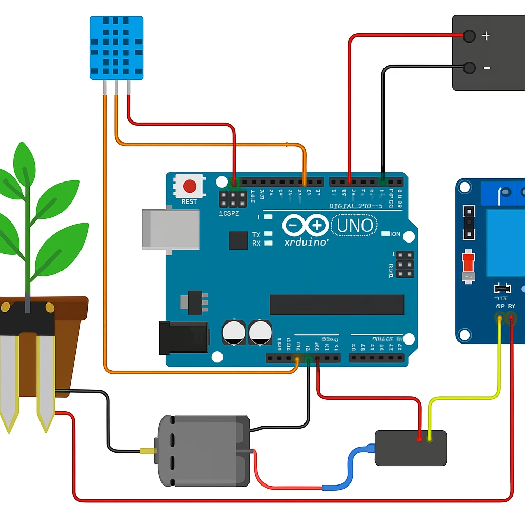
📷 Concept Illustration Idea
Image should show:
- A potted plant with soil moisture sensor
- Arduino + relay + pump setup
- Water tube delivering water
- Cloud icon pulling weather data
- Smartphone with “Moisture: Low. Watering…” message
✅ Applications
- Urban gardening
- Agricultural automation
- Greenhouse management
- AI botany research
- Elderly or remote plant caretaking
⚠️ Safety & Final Notes
Ensure waterproofing of electronics.
Use safe voltage pumps (e.g., 5–12V DC).
AI logic should be tested carefully before hands-off deployment.
You are responsible for ensuring no over-watering or electrical hazards occur.
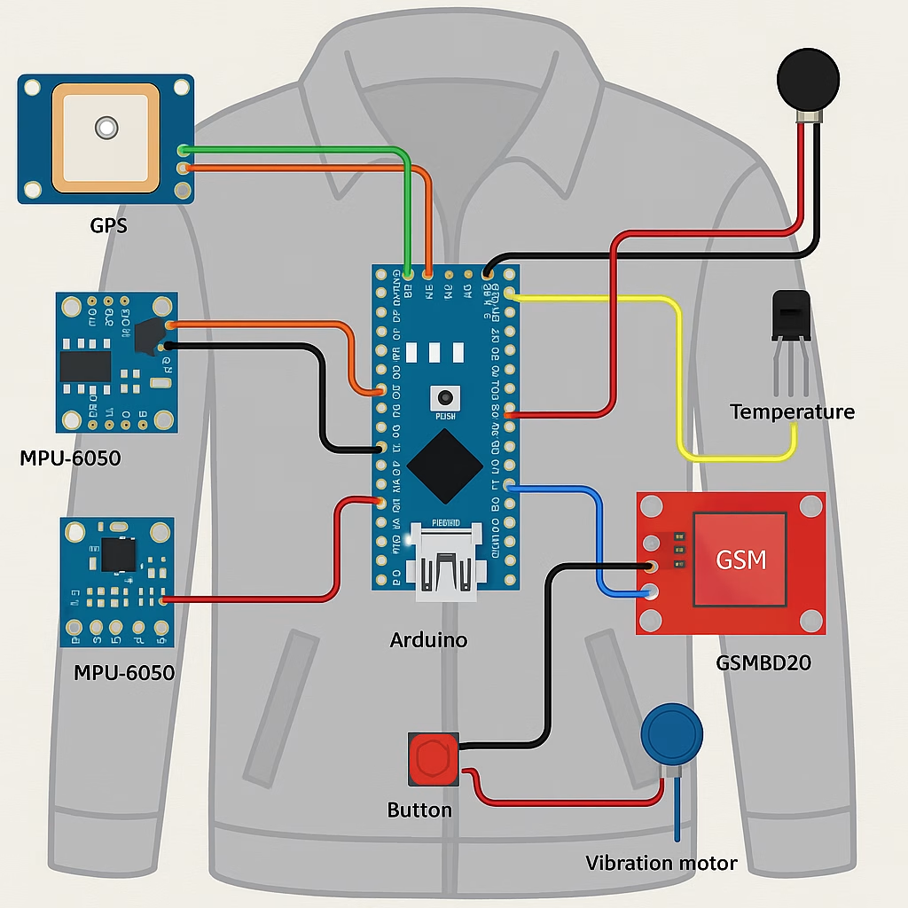
4. 🧥 Arduino Smart Jacket (Wearable Safety System)
A wearable jacket that includes GPS + fall detection + temperature sensors, sending alerts to emergency contacts if the wearer is in danger.
Applications:
- Elderly safety
- Hikers and mountaineers
- Smart clothing industry
🚨 Project Overview
This wearable safety device is built into a jacket and monitors:
- GPS location
- Sudden falls or impacts
- Body/ambient temperature
It automatically sends an alert with GPS coordinates to emergency contacts via GSM or Wi-Fi, ensuring rapid response in case of accidents or medical emergencies.
🧩 Components Required
| Component | Qty | Function |
|---|---|---|
| Arduino Nano / Uno | 1 | Main controller |
| MPU6050 Accelerometer/Gyroscope | 1 | Fall detection (motion sensing) |
| GPS Module (NEO-6M) | 1 | Gets live location |
| GSM Module (SIM800L) / ESP8266 | 1 | Sends SMS or connects to cloud |
| Temperature Sensor (DS18B20 / DHT11) | 1 | Reads ambient/body temperature |
| 3.7V LiPo Battery + Charging Module | 1 | Power supply |
| Push Button (SOS) | 1 | Manual emergency trigger |
| Vibration Motor or Buzzer | 1 | Feedback alert |
| Soft fabric wiring / conductive thread | – | For wearable integration |
🧠 System Logic
- Real-time Monitoring
- Tracks movement and tilt via MPU6050.
- Detects abnormal acceleration = fall.
- Temperature Sensing
- Detects dangerous body temps (hypothermia or fever).
- GPS + Alert
- Acquires coordinates using GPS.
- Sends an SMS with location to predefined contacts if:
- A fall is detected
- The SOS button is pressed
- Dangerous temp is recorded
🔌 Wiring Summary
🔴 MPU6050
- VCC → 3.3V / 5V
- GND → GND
- SDA → A4
- SCL → A5
🟡 GPS (NEO-6M)
- TX → D4 (SoftwareSerial RX)
- RX → D3 (SoftwareSerial TX)
- VCC → 3.3V / 5V
- GND → GND
🟢 GSM (SIM800L)
- TX → D7
- RX → D8
- VCC → External 3.7V
- GND → GND
🔵 Temperature Sensor (DS18B20)
- DATA → D2
- VCC → 5V
- GND → GND
- 4.7kΩ pull-up resistor between DATA and VCC
🔘 SOS Button
- One side → GND
- Other side → D9 (with internal pull-up)
👨💻 Arduino Code (Core Logic Example)
#include <SoftwareSerial.h>
#include <OneWire.h>
#include <DallasTemperature.h>
#include <Wire.h>
#include <Adafruit_MPU6050.h>
#include <Adafruit_Sensor.h>

#define ONE_WIRE_BUS 2
#define SOS_PIN 9

SoftwareSerial gpsSerial(4, 3);
SoftwareSerial gsmSerial(7, 8);
OneWire oneWire(ONE_WIRE_BUS);
DallasTemperature sensors(&oneWire);
Adafruit_MPU6050 mpu;

float accThreshold = 2.5;

void setup() {
  Serial.begin(9600);
  sensors.begin();
  mpu.begin();
  pinMode(SOS_PIN, INPUT_PULLUP);
  gpsSerial.begin(9600);
  gsmSerial.begin(9600);
  delay(1000);
}

void loop() {
  sensors.requestTemperatures();
  float tempC = sensors.getTempCByIndex(0);

  sensors_event_t a, g, temp;
  mpu.getEvent(&a, &g, &temp);

  float accTotal = sqrt(a.acceleration.x * a.acceleration.x +
                        a.acceleration.y * a.acceleration.y +
                        a.acceleration.z * a.acceleration.z);

  bool fallDetected = accTotal > accThreshold;
  bool sosPressed = digitalRead(SOS_PIN) == LOW;
  bool tempAbnormal = (tempC > 38.5 || tempC < 35.0);

  if (fallDetected || sosPressed || tempAbnormal) {
    sendAlert(tempC);
  }

  delay(5000);
}

void sendAlert(float temp) {
  String gpsData = readGPS();
  gsmSerial.println("AT+CMGF=1");
  delay(1000);
  gsmSerial.println("AT+CMGS=\"+1234567890\""); // Replace
  delay(1000);
  gsmSerial.print("ALERT! Fall/Temperature Event Detected.\nTemp: ");
  gsmSerial.print(temp);
  gsmSerial.print("C\nGPS: ");
  gsmSerial.print(gpsData);
  gsmSerial.write(26);
  delay(5000);
}

String readGPS() {
  String location = "";
  while (gpsSerial.available()) {
    char c = gpsSerial.read();
    location += c;
  }
  return location;
}
📐 Wearable Integration
- Embed Arduino & modules in a pocket or internal pouch.
- Use conductive thread to wire sensors to sleeves/shoulders.
- Place fall sensor (MPU6050) near upper back or shoulders.
- GPS antenna should face up or outwards.
- Waterproof everything using fabric-friendly covers.
📱 Optional Smartphone Interface
- Use Blynk, Firebase, or custom app to receive alerts.
- Show:
- Location on map
- Current temperature
- Fall detection status
📸 Visual Concept (Diagram Suggestion)
- Jacket with modules mapped out:
- GPS on shoulder
- Fall sensor on back
- Arduino near chest
- Push-button on sleeve
- Buzzer or vibration motor inside
✅ Use Cases
- Elderly people living alone
- Children or people with medical risks
- Hikers / trekkers / mountain climbers
- Construction workers
- Smart wearable prototypes
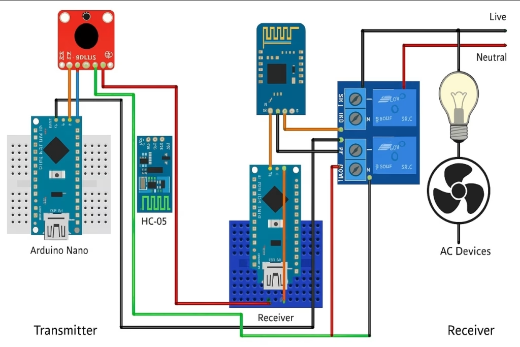
5. 🏡 Gesture-Controlled Home Automation System
Control lights, fans, and appliances with hand gestures using Arduino + Accelerometers. Popular among DIY home automation fans and disabled users.
Modules used:
- Arduino Nano
- ADXL345 Accelerometer
- RF or Bluetooth Modules
Control your home devices using hand gestures — wave your hand to turn on/off lights, fans, or appliances!
🎯 Project Objectives
- Use hand gestures to wirelessly control devices.
- Great for accessibility, DIY home automation, or futuristic control.
- Wireless control via Bluetooth or RF module.
🧩 Components Needed
| Component | Qty | Description |
|---|---|---|
| Arduino Nano / Uno | 1 | Microcontroller |
| ADXL345 Accelerometer | 1 | Detects tilt/gesture |
| HC-05 Bluetooth Module | 1 | Wireless communication |
| Relay Module (2/4 channel) | 1 | Controls AC appliances |
| Power Supply (5V) | 1 | For Arduino and relay |
| AC Devices (Bulb, Fan…) | — | Devices to control |
🔧 System Overview
- Accelerometer detects gesture →
- Arduino interprets gesture as a command →
- Bluetooth module sends signal to receiver Arduino →
- Relay module turns device ON/OFF accordingly.
👨🏭 Two Arduino Setup (Transmitter + Receiver)
- Transmitter Arduino (Hand Unit):
- Reads ADXL345 data.
- Sends gesture code over Bluetooth.
- Receiver Arduino (Home Base):
- Listens via Bluetooth.
- Turns relays ON/OFF based on received code.
🛠️ Wiring: Transmitter (Hand Unit)
🔵 ADXL345
- VCC → 3.3V
- GND → GND
- SDA → A4
- SCL → A5
🔵 HC-05 Bluetooth
- TX → D10 (SoftSerial RX)
- RX → D11 (with 1kΩ-2kΩ voltage divider)
- VCC → 5V
- GND → GND
💡 Wiring: Receiver (Relay Control)
🔵 HC-05 Bluetooth
- TX → D10
- RX → D11 (with voltage divider)
- VCC → 5V
- GND → GND
🔌 Relay Module
- IN1, IN2 → Arduino D2, D3
- VCC → 5V
- GND → GND
- NO/NC → Appliance Live Line
👨💻 Sample Arduino Code (Transmitter)
#include <Wire.h>
#include <Adafruit_ADXL345_U.h>
#include <SoftwareSerial.h>

Adafruit_ADXL345_Unified accel = Adafruit_ADXL345_Unified();
SoftwareSerial BTSerial(10, 11);

void setup() {
  Serial.begin(9600);
  BTSerial.begin(9600);
  accel.begin();
}

void loop() {
  sensors_event_t event;
  accel.getEvent(&event);

  float x = event.acceleration.x;
  float y = event.acceleration.y;

  if (x > 5) {
    BTSerial.println("LIGHT_ON");
  } else if (x < -5) {
    BTSerial.println("LIGHT_OFF");
  } else if (y > 5) {
    BTSerial.println("FAN_ON");
  } else if (y < -5) {
    BTSerial.println("FAN_OFF");
  }

  delay(500);
}
👨💻 Sample Arduino Code (Receiver)
#include <SoftwareSerial.h>

SoftwareSerial BTSerial(10, 11);
#define RELAY1 2
#define RELAY2 3

void setup() {
  Serial.begin(9600);
  BTSerial.begin(9600);
  pinMode(RELAY1, OUTPUT);
  pinMode(RELAY2, OUTPUT);
}

void loop() {
  if (BTSerial.available()) {
    String command = BTSerial.readStringUntil('\n');
    if (command == "LIGHT_ON") digitalWrite(RELAY1, HIGH);
    if (command == "LIGHT_OFF") digitalWrite(RELAY1, LOW);
    if (command == "FAN_ON") digitalWrite(RELAY2, HIGH);
    if (command == "FAN_OFF") digitalWrite(RELAY2, LOW);
  }
}
💡 Example Gesture Mapping
| Gesture Direction | Action |
|---|---|
| Tilt Right (X+) | Light ON |
| Tilt Left (X−) | Light OFF |
| Tilt Up (Y+) | Fan ON |
| Tilt Down (Y−) | Fan OFF |
📱 Optional
- You can use RF modules instead of Bluetooth for simpler wireless transmission.
- For mobile app integration, add Blynk or MIT App Inventor.
🔐 Safety Tips
- Never connect relay modules directly to mains without protection.
- Use proper insulation and enclosures.
- Test with low-voltage appliances first.
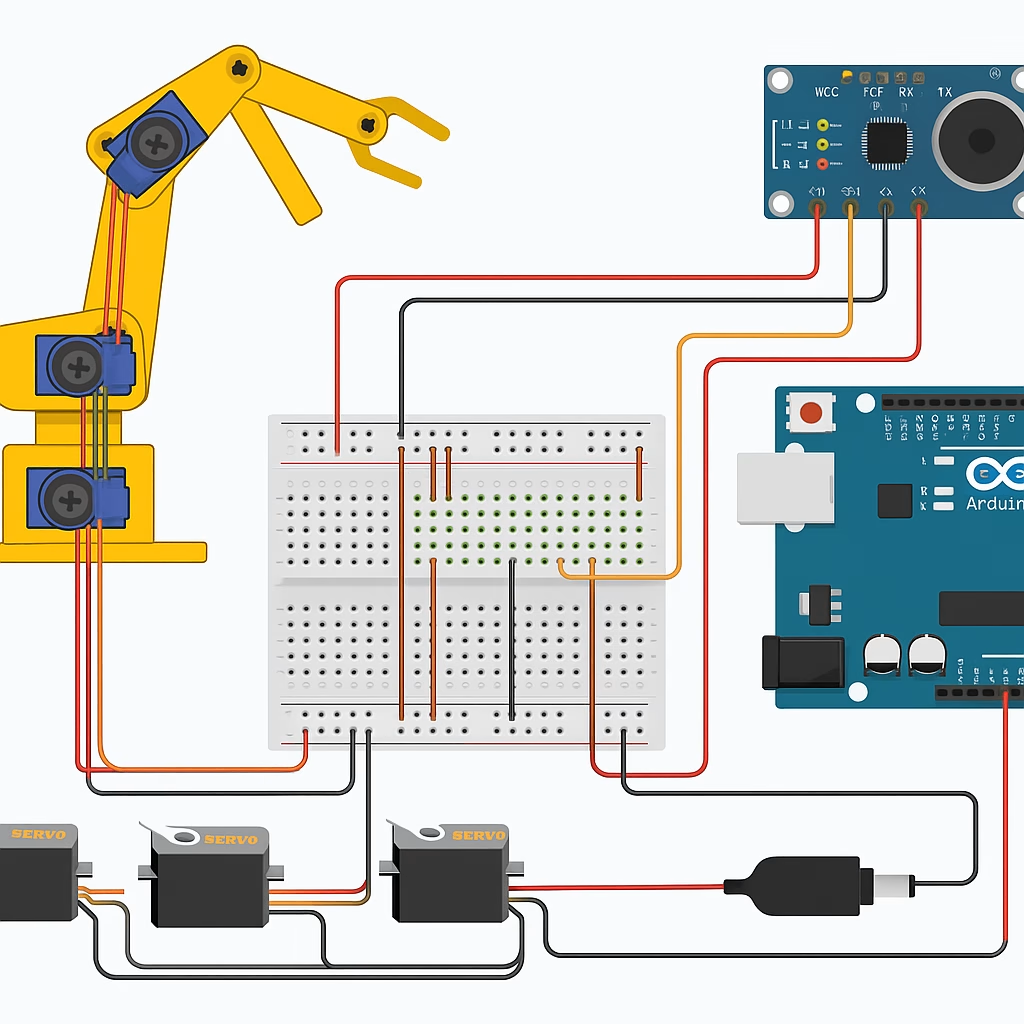
🗣️ Voice-Controlled Robotic Arm
An Arduino-controlled robotic arm that responds to voice commands using speech recognition modules. A great example of low-cost human-robot interaction.
Ideal for:
- STEM education
- Industrial training
- Prosthetics development
A robotic arm that moves in response to spoken commands using Arduino and a speech recognition module.
🎯 Project Goal
- Control a robotic arm without physical input.
- Use voice commands like “left”, “right”, “grab”, etc.
- Teach real-world applications of AI, robotics, and embedded systems.
🧩 Required Components
| Component | Qty | Description |
|---|---|---|
| Arduino Uno / Nano | 1 | Main controller |
| Speech Recognition Module (like Elechouse V3) | 1 | Captures voice commands |
| Robotic Arm (4-5 DOF or custom servo-based) | 1 | Mechanical structure |
| Servo Motors (SG90 or MG996R) | 4–6 | Joint movements |
| External 5V Power Supply | 1 | For powering multiple servos |
| Jumper wires + Breadboard | — | Connections |
| Microphone (if external) | 1 | For voice input (on module or wired) |
🧠 Basic Working Principle
- User speaks into mic: “LEFT”, “PICK”, etc.
- The Speech Recognition Module processes the command.
- Arduino receives the decoded instruction via Serial.
- Arduino controls the servo motors accordingly.
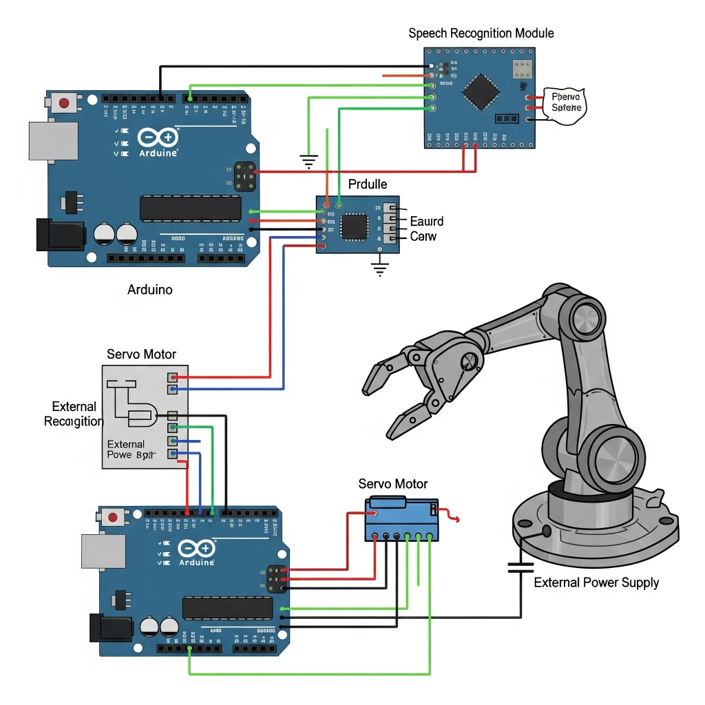
🛠️ Circuit Connections
🔹 Speech Recognition Module (Elechouse V3)
- VCC → 5V
- GND → GND
- TX → Arduino RX (D0 or SoftwareSerial RX)
- RX → Arduino TX (D1 or SoftwareSerial TX)
🔹 Servo Motors
- Signal Wires → D2, D3, D4, D5, D6…
- VCC → External 5V supply
- GND → Common GND with Arduino
⚠️ Do not power servos directly from Arduino — use an external power source (battery or adapter with 5V regulator).
⚙️ Robotic Arm Movements
| Command | Action |
|---|---|
| “LEFT” | Rotate base left |
| “RIGHT” | Rotate base right |
| “UP” | Arm up |
| “DOWN” | Arm down |
| “GRAB” | Close gripper |
| “RELEASE” | Open gripper |
👨💻 Sample Arduino Code
#include <Servo.h>
Servo base, shoulder, elbow, gripper;
String voice;

void setup() {
  Serial.begin(9600);
  base.attach(2);
  shoulder.attach(3);
  elbow.attach(4);
  gripper.attach(5);
}

void loop() {
  if (Serial.available()) {
    voice = Serial.readStringUntil('\n');
    voice.trim();

    if (voice == "LEFT") base.write(45);
    else if (voice == "RIGHT") base.write(135);
    else if (voice == "UP") shoulder.write(60);
    else if (voice == "DOWN") shoulder.write(120);
    else if (voice == "GRAB") gripper.write(20);
    else if (voice == "RELEASE") gripper.write(90);
  }
}
🎤 Training the Voice Module
If you’re using Elechouse V3:
- Train it using buttons on the module or via the included software.
- Each command (like “left”, “right”, etc.) is stored in a slot (e.g., Group 1, Command 1).
- Arduino reads the recognized command number and maps it to an action.
🎓 Applications
- 💼 Prosthetics Prototypes – mimic human limb control.
- 🏭 Industry Robots – teach via spoken instruction.
- 👨🏫 STEM Learning Kits – intro to robotics & AI.
- 🧠 Assistive Tech – improve accessibility.
⚠️ Safety Notes
- Test arm movement with lightweight loads first.
- Use servos with metal gears for stronger loads.
- Always power off when making adjustments.
📌 Final Note
This project is for educational use and not certified for medical or industrial applications.
Misuse or incorrect wiring can cause damage. Proceed under supervision and follow electrical safety practices.
💡 How to Start Building Your Own Invention?
- Choose a real-world problem.
- Define the sensors and modules needed.
- Sketch the circuit diagram.
- Write the Arduino code (C/C++).
- Test, iterate, and improve.
Tip: Use platforms like Tinkercad, Fritzing, or Arduino IDE Web Editor for easier prototyping.
📷 Gallery: Inspiration from Real Arduino Projects
| Project | Description | Key Modules |
|---|---|---|
| Smart Cane for the Blind | Uses ultrasonic sensors to detect obstacles | Arduino Uno, Buzzer, Ultrasonic Sensor |
| Biometric Locker | Uses fingerprint scanner for access | Arduino Nano, Fingerprint Sensor |
| Weather Balloon | Sends climate data from high altitudes | Arduino Mini, GPS, Temperature Sensor |
⚠️ Safety & Legal Disclaimer
This project is intended solely for educational and prototyping purposes. These systems, generated with artificial intelligence logic, must be carefully tested before any real-world implementation.
All actions, implementations, and outcomes resulting from this project are entirely the responsibility of the developer or individual applying the system.
For real-life deployment, the system must be equipped with proper sensors, protective housings, safety mechanisms, and comply with local legal regulations.
Any misuse or misinterpretation of the project that results in device damage, data loss, or accidental injury is entirely the user’s responsibility.
Always use the project responsibly and perform extensive testing before any live or field deployment.
Supervision & Controls
Especially for users with limited electronics experience, including children, it is strongly advised to work under the constant supervision of an experienced adult or professional when assembling or testing such projects.