Topic Summary:
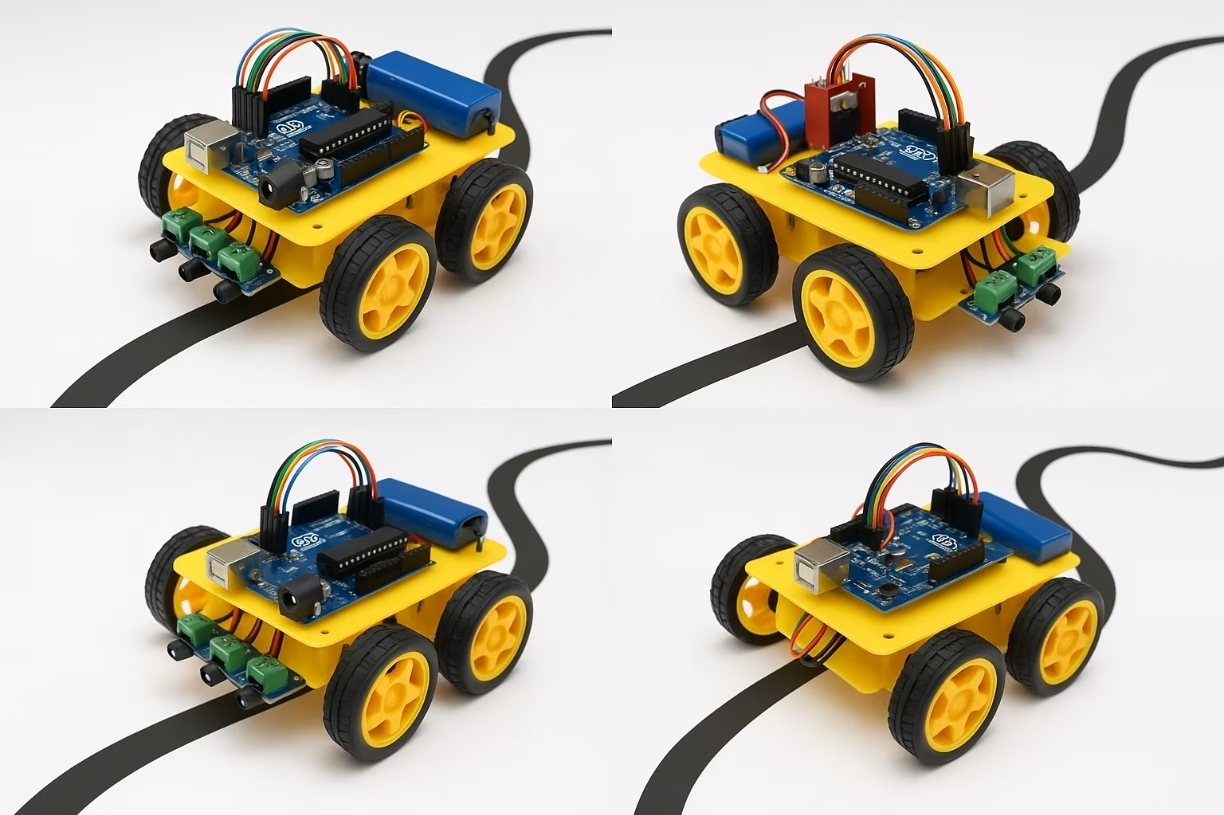
This project involves building a robot that automatically follows a black line on the ground using Arduino. The robot detects contrast differences using IR (infrared) sensors and adjusts its direction by sending signals to its motors.

Objectives:
- Learn basic robotic motion control
- Understand the sensor-motor relationship
- Practice Arduino programming
- Experiment with real-time decision-making algorithms
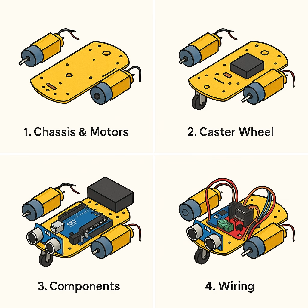
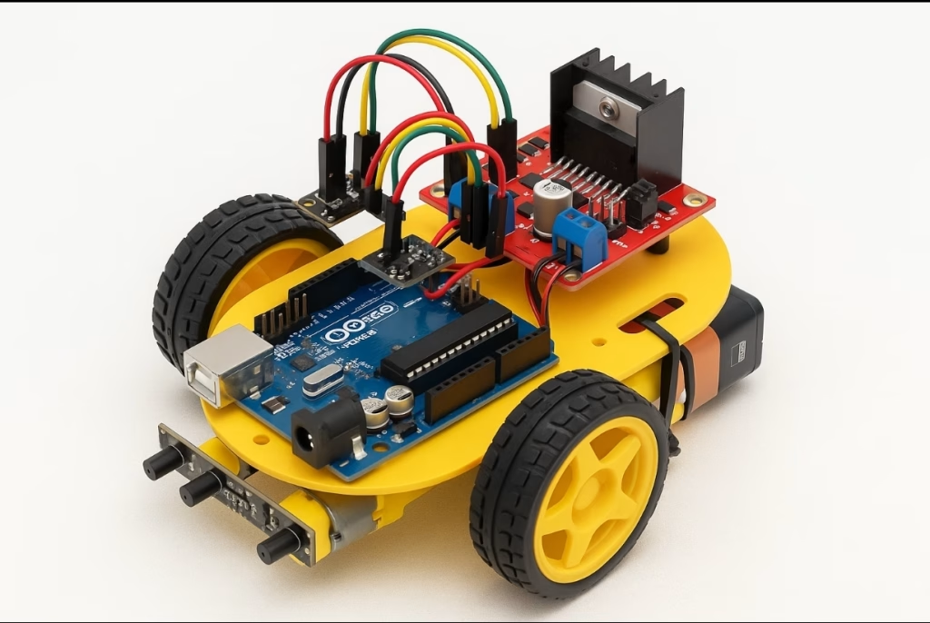
Project Components:
- Arduino Uno
- 2 DC motors + motor driver (L298N or L9110)
- 2 or 3 IR sensors (for line detection)
- Robot chassis + wheels
- 9V battery or 18650 battery
- Jumper wires
Programming Logic:
Based on the input from IR sensors, the robot sends power to motors. For example:
- Middle sensor detects black: Move forward
- Left sensor detects black: Turn left (by speeding up right motor)
- Right sensor detects black: Turn right (by speeding up left motor)
- No sensor detects black: Stop (line lost)
Extension Ideas:
- Add Bluetooth module (e.g., HC-05) for remote control
- Display sensor readings on an LCD screen
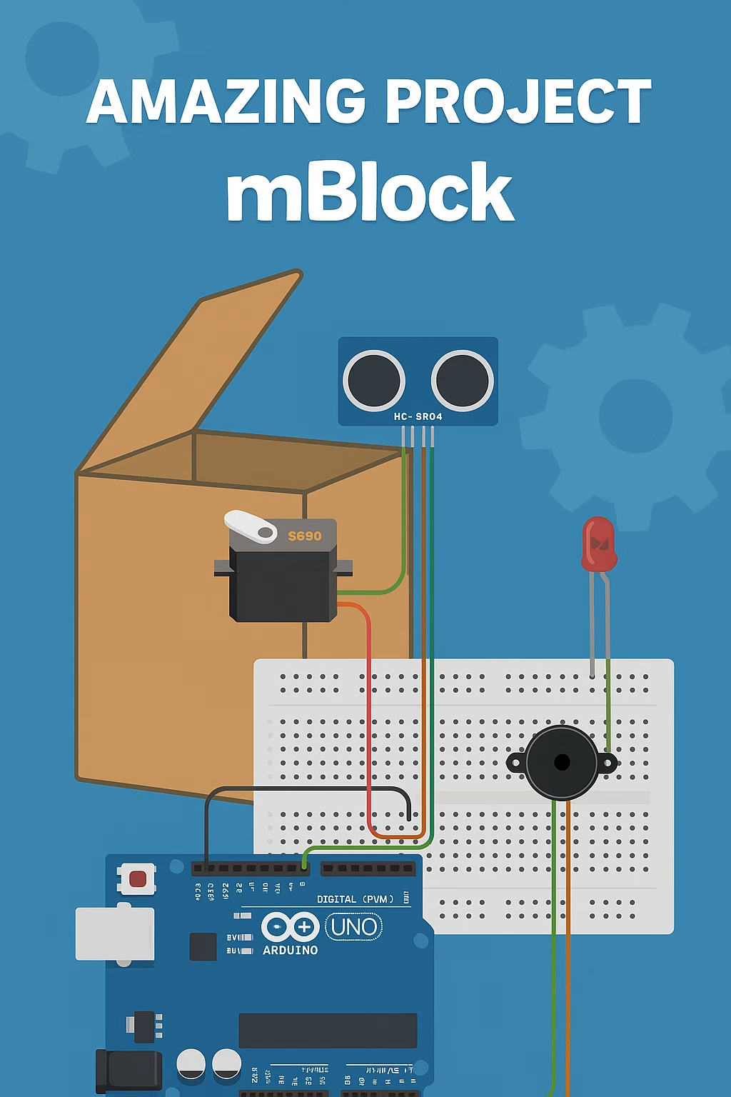
- Add obstacle avoidance sensor (e.g., ultrasonic)
- Use a color sensor for colored line tracking
Application Areas:
- Industrial automation
- Smart warehouse systems
- Autonomous delivery robots
- STEM education projects
Let’s start by creating the detailed project package for the “Arduino-Controlled Line Following Robot.”
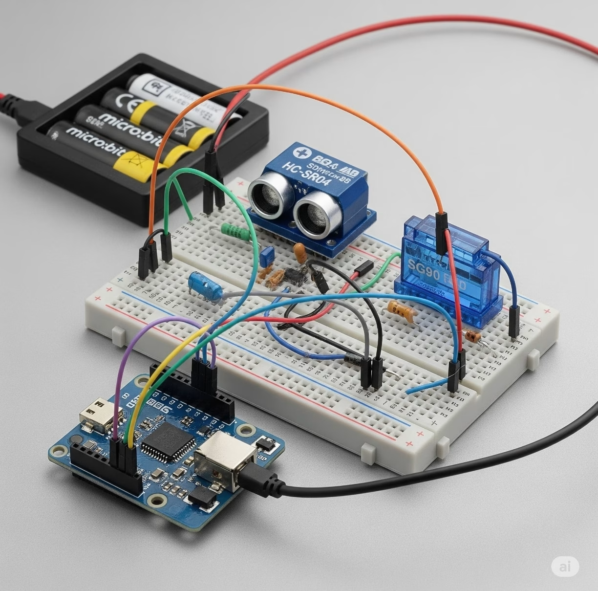
✅ 1. Circuit Diagram
Components:
- Arduino Uno
- L298N Motor Driver
- 2 DC motors
- 3 IR sensors (QRE1113 or TCRT5000 modules)
- 9V Battery or 2x 18650 cells
- Jumper wires
Basic Wiring Overview:
- IR Sensors:
- VCC → 5V
- GND → GND
- OUT (Left) → Arduino pin 2
- OUT (Center) → Arduino pin 3
- OUT (Right) → Arduino pin 4
- Motor Driver (L298N):
- IN1/IN2 → Arduino pins 9/10 (Left motor)
- IN3/IN4 → Arduino pins 5/6 (Right motor)
- ENA/ENB → connect to 5V or control with PWM for speed
- Motor A/B to DC motors
- 12V & GND from battery to L298N power input
—🔌 Wiring Instructions for Arduino-Controlled Line Following RobotFollow these steps to wire your components:
—1. IR Sensors (TCRT5000 or similar)You will use 2 or 3 IR sensors.
Here’s how to connect each:VCC (Power): Connect to 5V pin on the ArduinoGND (Ground):
Connect to GND on the ArduinoOUT (Signal):Left sensor → Digital Pin 2Center sensor → Digital Pin 3Right sensor → Digital Pin 4
—2. L298N Motor Driver ModuleMotor Connections:
Connect the left DC motor to OUT1 and OUT2 Connect the right DC motor to OUT3 and OUT4 Control Pins (from Arduino):IN1
→ Digital Pin 9IN2 → Digital Pin 10IN3
→ Digital Pin 5IN4 → Digital Pin 6Power:12V and GND pins on L298N should be connected to battery (9V or 2×18650)5V output on L298N can be used to power the Arduino (only if jumper is in place)Connect GND of battery and Arduino together
—3. Arduino BoardConnect all signal wires from IR sensors and motor driver as described Upload the control code from your computer via USB cablePower the board using USB or via the motor driver if configured

Aplication Code
const int leftSensor = 2;
const int centerSensor = 3;
const int rightSensor = 4;
const int motorLeftIN1 = 9;
const int motorLeftIN2 = 10;
const int motorRightIN3 = 5;
const int motorRightIN4 = 6;
void setup() {
pinMode(leftSensor, INPUT);
pinMode(centerSensor, INPUT);
pinMode(rightSensor, INPUT);
pinMode(motorLeftIN1, OUTPUT);
pinMode(motorLeftIN2, OUTPUT);
pinMode(motorRightIN3, OUTPUT);
pinMode(motorRightIN4, OUTPUT);
}
void loop() {
int left = digitalRead(leftSensor);
int center = digitalRead(centerSensor);
int right = digitalRead(rightSensor);
if (center == LOW && left == HIGH && right == HIGH) {
moveForward();
} else if (left == LOW) {
turnLeft();
} else if (right == LOW) {
turnRight();
} else {
stopMotors();
}
}
void moveForward() {
digitalWrite(motorLeftIN1, HIGH);
digitalWrite(motorLeftIN2, LOW);
digitalWrite(motorRightIN3, HIGH);
digitalWrite(motorRightIN4, LOW);
}
void turnLeft() {
digitalWrite(motorLeftIN1, LOW);
digitalWrite(motorLeftIN2, HIGH);
digitalWrite(motorRightIN3, HIGH);
digitalWrite(motorRightIN4, LOW);
}
void turnRight() {
digitalWrite(motorLeftIN1, HIGH);
digitalWrite(motorLeftIN2, LOW);
digitalWrite(motorRightIN3, LOW);
digitalWrite(motorRightIN4, HIGH);
}
void stopMotors() {
digitalWrite(motorLeftIN1, LOW);
digitalWrite(motorLeftIN2, LOW);
digitalWrite(motorRightIN3, LOW);
digitalWrite(motorRightIN4, LOW);
}
📦 Do You Need Any Libraries?
No additional libraries are required for the basic line-following robot code you’re using. Everything works with built-in Arduino functions like:
pinMode()digitalRead()digitalWrite()
These functions are part of the Arduino core, so no #include statements are needed at the top of your code.
✅ Why There’s No #include in the Code
Because:
- IR sensors use simple digital outputs → read with
digitalRead() - L298N motor driver is controlled via digital pins → write with
digitalWrite() - No LCD, Bluetooth, ultrasonic, or other modules are used in the basic version
So the code works out of the box in Arduino IDE — just copy, paste, and upload.
📚 When Would You Need Libraries?
| Feature | Required Library |
|---|---|
| I2C LCD Display | LiquidCrystal_I2C.h |
| Bluetooth Module (HC-05) | SoftwareSerial.h |
| Ultrasonic Sensor | NewPing.h (optional) |
| OLED Display (SSD1306) | Adafruit_SSD1306.h |
| Motor Shield or Encoders | Depends on the module |
🧪 Example: If You Use an I2C LCD
#include <Wire.h>
#include <LiquidCrystal_I2C.h>

LiquidCrystal_I2C lcd(0x27, 16, 2);
📡 Example: If You Add Bluetooth (HC-05)
#include <SoftwareSerial.h>

SoftwareSerial BT(7, 8);  // RX, TX
🔚 Summary
✅ The basic line follower code needs no libraries
✅ It is 100% compatible with Arduino Uno and IDE by default
✅ Add libraries only if you expand the project with displays, communication modules, or advanced sensors


")